
Network
This page covers the router’s wired and local network settings. You can change these settings from the local Web UI when you are on-site; overlapping customer-facing fields are also available from cloud Router Settings when the router is online.
For cellular, see Cellular & SIM; for using another WiFi network as an uplink, see Upstream WiFi.
Where to make the change
Section titled “Where to make the change”| Task | Local Web UI location | Cloud portal location |
|---|---|---|
| Wired internet | Network - WAN | Device Router Settings - Internet connection |
| Local address and DHCP | Network - LAN | Device Router Settings - Local network |
| Ethernet port roles, LAN/guest VLAN IDs, and tagged network | Network - LAN (Ethernet Port Roles and Tagged VLAN cards) | Device Router Settings - Local network |
| DNS | System - General | Device Router Settings - Device name, time & DNS |
| Failover order | Routing - WAN Failover | Device Router Settings - Internet connection |
| Port forwarding | Routing - Port Forwarding | Device Router Settings - Inbound port rules |
| Passthrough, cellular DMZ, or WAN bridge | Network - Passthrough / Bridge | Device Router Settings - Passthrough / bridge |
| Automatic connection diagnostics | Network - Diagnostics | Device Router Settings - Network diagnostics |
Local changes apply directly. Cloud changes are sent as jobs and require the router to be online.
WAN (wired internet)
Section titled “WAN (wired internet)”Configure the wired internet connection under Network - WAN.
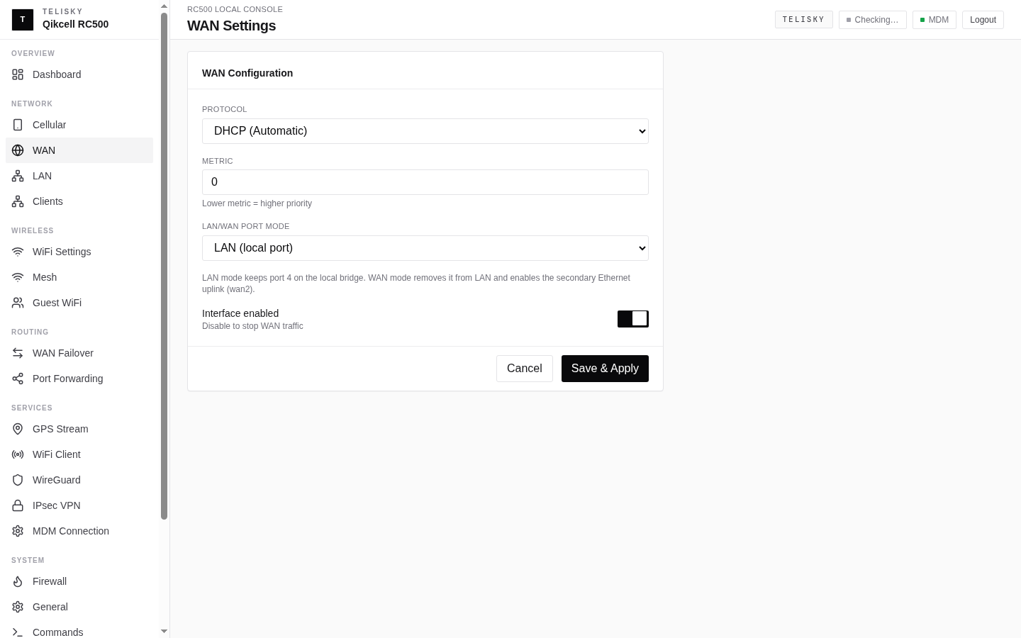
| Type | Use case |
|---|---|
| DHCP | Automatic IP from an upstream router or modem (most common) |
| Static IP | A fixed IP your provider assigned |
| PPPoE | Provider links that require PPPoE sign-in |
Passthrough and bridge modes
Section titled “Passthrough and bridge modes”Use Network - Passthrough / Bridge locally, or Passthrough / bridge in cloud Router Settings, when a downstream device needs its own routed segment, direct inbound cellular traffic, or a transparent wired path. Selected client ports are removed from the normal LAN while passthrough is enabled.
| Mode | What it does | Use it when |
|---|---|---|
| Routed NAT | Gives selected client ports a private subnet and routes them through the preferred uplink. Normal failover can still provide a fallback path. | A downstream router or appliance needs an isolated private network with outbound internet access. |
| Cellular DMZ | Keeps the static carrier IPv4 address on the RC500 and sends all unsolicited IPv4 traffic for that address to one private client by 1:1 NAT. | One downstream appliance must receive inbound cellular traffic while the RC500 remains connected to MDM. |
| WAN bridge | Creates a true Ethernet layer-2 bridge from either the dedicated WAN Port or LAN/WAN Port 4 to selected LAN client ports. Upstream DHCP and non-IP Ethernet frames pass through the bridge. | A downstream device must connect transparently to equipment attached to a wired uplink port. |
Cellular DMZ requirements
Section titled “Cellular DMZ requirements”Cellular DMZ is a 1:1-NAT pseudobridge, not a layer-2 bridge. Cellular QMI/raw-IP interfaces cannot join an Ethernet bridge.
- The cellular plan must provide a static, publicly reachable IPv4 address. CGNAT cannot accept unsolicited inbound connections.
- Select exactly one client port and give its downstream device the configured private DMZ client address, either by passthrough DHCP or static configuration.
- Enter the carrier IPv4 address exactly as assigned. If the carrier changes that address, update the setting before relying on inbound access.
- The RC500 retains the carrier address, so its cellular MDM session can remain online.
Wired bridge requirements
Section titled “Wired bridge requirements”WAN bridge uses either the physical WAN Port or flexible LAN/WAN Port 4 as the upstream side. The selected uplink cannot also be a client port. While bridge mode is active, that port is dedicated to the layer-2 bridge and is unavailable as a normal routed uplink for the RC500.
Apply and rollback safety
Section titled “Apply and rollback safety”Passthrough changes can interrupt the browser session or move the port you are using out of the normal LAN. Review the client-port list before applying.
- Local Web UI: the router arms a rollback timer before changing the network. After confirming that the downstream connection and router management path both work, use Confirm before the timer expires.
- Cloud portal: the apply job uses an automatic five-minute safety timer, polls the router’s apply status, and confirms it automatically. Treat the change as complete only when the job reports Succeeded; a failed apply is not reported as success.
Preserve MDM prevents the passthrough configuration from intentionally consuming the management path, but it does not create connectivity. Keep an independent active management uplink—such as cellular while using WAN bridge, or another WAN path while testing routed NAT. For remote changes, have an on-site or out-of-band recovery path available.
Connection priority and failover
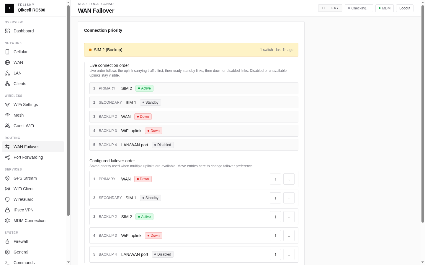
Section titled “Connection priority and failover”The RC500 can keep a site online by automatically switching between its internet connections. Set the order under Routing - WAN Failover locally, or from Internet connection in cloud Router Settings. The cloud can send the customer priority list to an online router as a job; the local Web UI applies the change directly on-site.
| Field | Description | Default |
|---|---|---|
| Connection priority | The order of connections used for failover | WAN, then SIM 1, SIM 2, WiFi uplink, LAN/WAN port |
| Live connection order | The current active / standby / down state of each connection | From router status |
| Health-check targets | Addresses used to test whether a connection really works | 8.8.8.8, 1.1.1.1 |
| Check interval | Seconds between checks | 60 |
| Failure threshold | Failed checks before a connection is treated as down | 3 |
| Recovery threshold | Good checks before a connection is treated as up again | 3 |
On single-modem units, SIM 1 and SIM 2 share one cellular connection and the modem handles SIM switching.
LAN (local network)
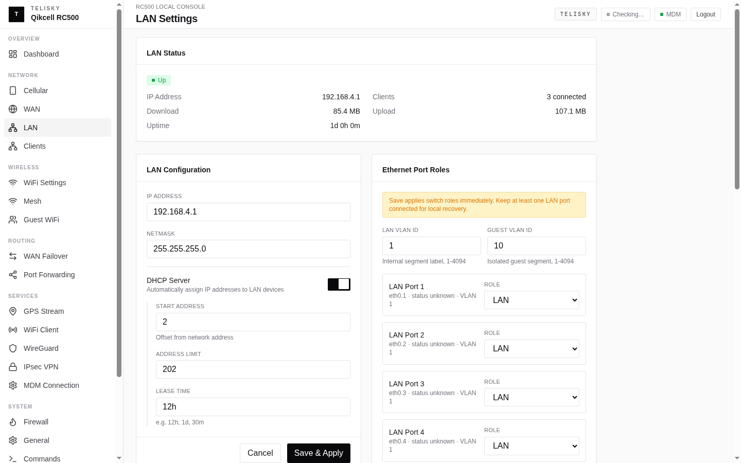
Section titled “LAN (local network)”Configure the router’s own network under Network - LAN.
| Field | Default | Description |
|---|---|---|
| IP address | 192.168.4.1 | The router’s address on its local network |
| Netmask | 255.255.255.0 | The local subnet |
DHCP server
Section titled “DHCP server”| Field | Default | Description |
|---|---|---|
| Enable DHCP | Enabled | Hand out addresses to connected devices |
| Start | 2 | First address offset in the range |
| Limit | 202 | How many addresses to hand out |
| Lease time | 12h | How long an address stays assigned |
With the default 192.168.4.1/24, the address pool starts at 192.168.4.2.
Reserved addresses
Section titled “Reserved addresses”Keep an important device on the same local IP by reserving it by hardware (MAC) address:
| Field | Description |
|---|---|
| Hostname | A friendly name |
| MAC address | The device’s hardware address |
| IP address | The local address to reserve for it |
Connected clients
Section titled “Connected clients”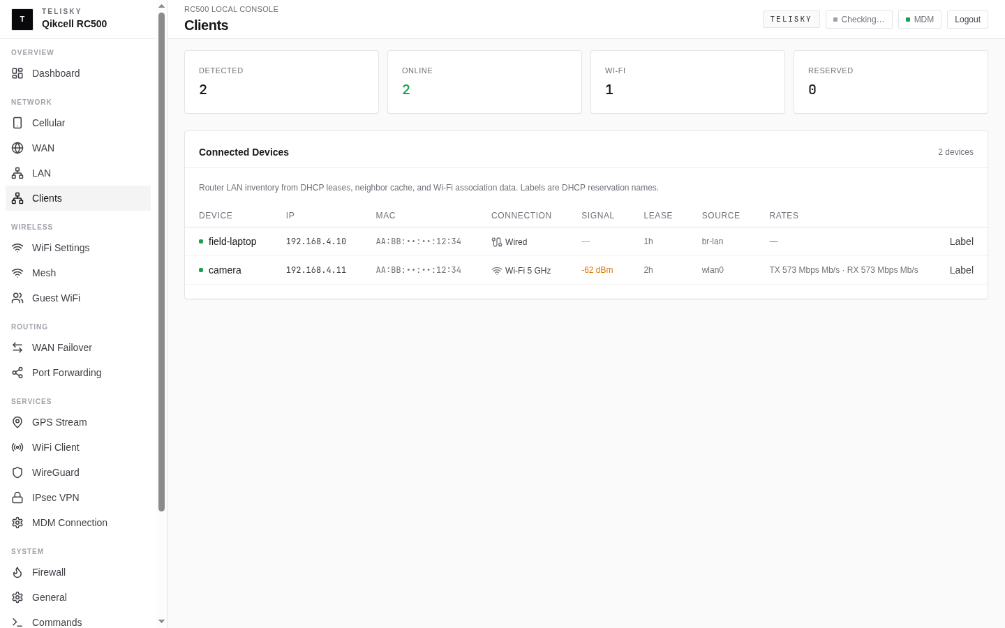
Ethernet port roles and guest VLAN
Section titled “Ethernet port roles and guest VLAN”Some deployments use the RC500 Ethernet ports for different jobs: normal LAN devices, a guest network, the flexible LAN/WAN Port 4, or one optional tagged network for equipment that expects a specific VLAN tag. Configure these settings from the Network - LAN page on-site—use the Ethernet Port Roles and Tagged VLAN cards—or from Router Settings - Local network in the cloud when the router is online. Use those guided controls rather than editing low-level network files by hand.
| Field | What it means |
|---|---|
| Port role | Access role for LAN Ports 1–4 only: main LAN, guest network, or disabled. Only LAN/WAN Port 4 may be set to a WAN path. The dedicated WAN Port is not part of this access-role list. |
| LAN VLAN ID | Custom VLAN ID for the main local network when your site requires a specific LAN ID. Use a whole number from 1 through 4094. |
| Guest VLAN ID | Custom VLAN ID that separates guest traffic from the main local network when guest access is enabled. Use a whole number from 1 through 4094. |
| Tagged network | One optional extra IEEE 802.1Q tag carried only on selected LAN Ethernet ports—layer-2 membership only |
| LAN/WAN Port 4 | The only access-role port that can stay on the local LAN or act as an additional WAN path |
Custom LAN and guest VLAN IDs
Section titled “Custom LAN and guest VLAN IDs”Set the LAN VLAN ID and Guest VLAN ID only when your wiring plan requires specific IDs. Leave the defaults when ports carry ordinary untagged LAN or guest traffic.
- VLAN IDs must be canonical whole numbers from
1through4094(no leading zeros, spaces, signs, exponents, or fractions). - LAN and guest VLAN IDs must be different from each other. The guided form rejects a duplicate ID.
- Access roles apply to LAN Ports 1–4 only. Only Port 4 may use the WAN role, and at least one port must remain on the LAN role.
- Assign a port to the guest network only when the device plugged into that port should be isolated from the main LAN.
- If you are not sure which cable goes to which equipment, leave port roles and VLAN IDs unchanged and ask the installer or Telisky Support.
Optional tagged network
Section titled “Optional tagged network”You can enable one optional tagged network. This is a single extra IEEE 802.1Q tag on selected LAN ports—layer-2 membership only—not a multi-VLAN trunk planner, and not a third RC500 network with its own IP address, routing, or DHCP.
- The tagged network is LAN-only. Select ports that currently show a normal LAN role (LAN Ports 1–3, or LAN/WAN Port 4 while it is still a LAN port). Ports set to WAN, guest/access-only, disabled, or used as passthrough/bridge clients are not eligible.
- Choose a free VLAN ID that is a whole number from
1through4094. The form rejects a tagged network ID that reuses the current LAN or guest VLAN ID. - Select only the LAN ports that should carry that one tag. Other LAN ports stay ordinary LAN ports and are not part of the tagged network.
Automatic removal when roles change
Section titled “Automatic removal when roles change”The router keeps the tagged network aligned with the live port roles. When a selected port can no longer carry it, the router removes that port from the tagged network, and removes the tagged network entirely if no eligible LAN ports remain. That happens when a selected port becomes:
- a WAN path (including LAN/WAN Port 4 used as WAN)
- guest or access-only
- disabled
- a passthrough or bridge client port
After a role or passthrough change, re-check Network - LAN (Ethernet Port Roles and Tagged VLAN) or cloud Local network before relying on the tagged path. You may need to choose a different eligible LAN port or turn the tagged network back on after the topology settles.
Apply and cloud jobs
Section titled “Apply and cloud jobs”VLAN and port-role changes affect live Ethernet paths. Local and cloud apply behave differently:
- Local Web UI: the change is applied transactionally (commit, reload, and device-side readback). If mutation, commit, reload, or readback fails, the router restores the previous working network settings. There is no operator confirmation timer on this path.
- Cloud portal: the change is queued as a job for an online router. Treat it as complete only after the job reports success from confirmed device readback and apply—not when the form is merely submitted.
Matching guided fields are available in both the local Web UI and cloud Router Settings. For the cloud form layout, see Router Settings - Local devices.
DNS is not on the LAN page. In the local Web UI, set DNS under System - General; in the cloud portal, use Router Settings - Device name, time & DNS. The router ships with public upstream DNS (8.8.8.8, 1.1.1.1) and rebind protection enabled.
Port forwarding
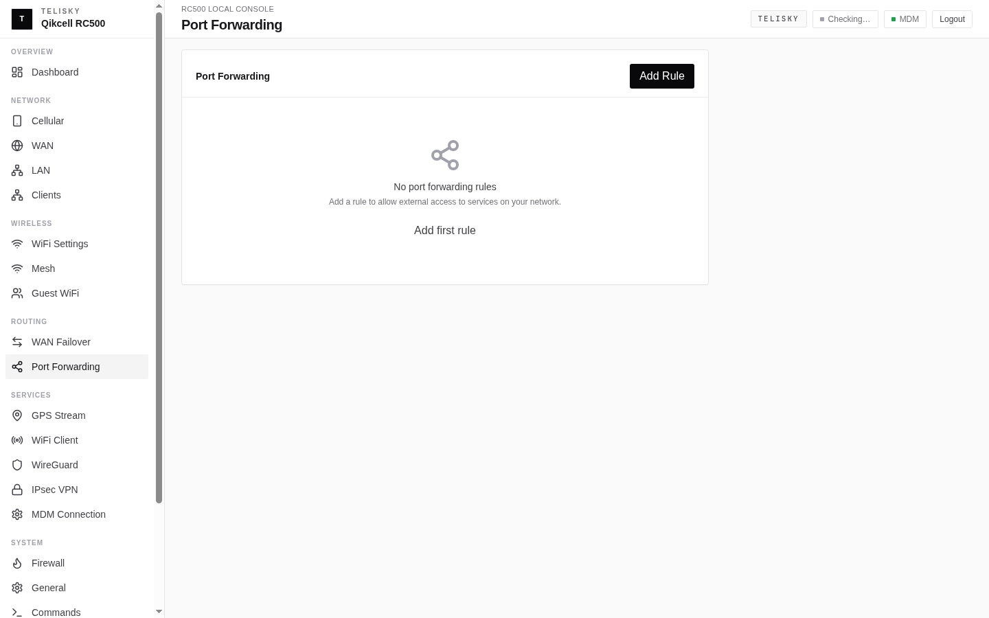
Section titled “Port forwarding”Port forwarding makes an internal device reachable from the internet - for example a camera or a server behind the router. Create rules under Routing - Port Forwarding locally, or follow Cloud Port Forwarding to add an Inbound port rule to one device from Router Settings.
| Field | Description |
|---|---|
| Name | A label for the rule |
| Protocol | TCP, UDP, or both |
| External port | The port that arrives from the internet |
| Internal IP | The local device to send it to |
| Internal port | The port on that device |
CGNAT warning
Section titled “CGNAT warning”Port forwarding only works if the internet connection gives the router a publicly reachable address. Many cellular plans use CGNAT, where the carrier does not assign a reachable public address - in that case inbound connections cannot reach the router no matter how the rule is set. The router warns when it detects this. See Internet & Cellular for options.
Firewall
Section titled “Firewall”The router includes a read-only firewall view. Customer-editable inbound rules are managed through port forwarding above. See Firewall.